CV Instrument
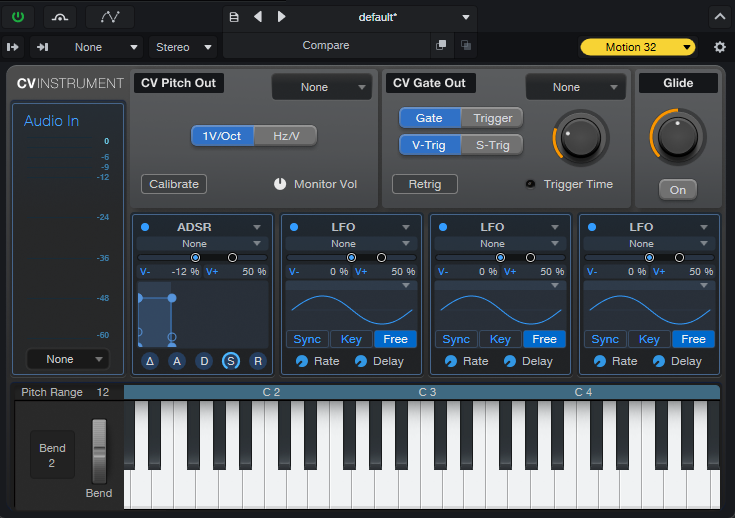
For Fender Studio Pro users with a hybrid (software and hardware) studio workflow and analog (modular or integrated) synthesizers, CV Instrument provides a way to control these directly using analog control voltages and trigger/gate signals.
Control Voltage (CV) is a means of controlling analog synthesizers and drum machines. While MIDI is used to control many modern synthesizers, drum machines and controllers digitally, many modular systems require CV. Whether your setup is semi-modular or you’re working with a full 48U wall of modular synthesizers, CV Instrument enables you to easily control your analog gear in Fender Studio Pro.
When combined with a compatible, multi-out audio interface, the CV Instrument can translate note trigger and pitch information from Instrument Tracks to analog triggers and control voltages, which are sent from the assigned interface outputs directly to the synthesizer’s control voltage inputs.
Additionally, the output signal from the external instrument can be monitored directly from the Fender Studio Pro's mixer. The CV Instrument even provides a calibration option to tune the connected oscillator and eliminate pitch drift.
The following sections will further detail each of the CV Instrument features and requirements.
Audio In
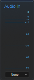
The Audio In section is used for more than just monitoring. Similar to Fender Studio Pro’s External Effect plug-in, the CV Instrument is a door to the external world.
With the CV Instrument, users can play external Synthesizers and include them into a Session as if they were software instruments. The external synthesizer will listen to CV signals as inputs and will output audio. CV signals are generated and sent to the synthesizer hardware, and you receive the audio from it as an input.
The Audio In section has the following features:
-
Audio Input: From the Audio In drop-down menu, select the appropriate hardware audio input where the audio is coming from. The Audio Input is used for both calibration and for monitoring the external instrument output through the Fender Studio Pro mixer. After calibration, make sure to connect the main output of the instrument (rather than the oscillator direct output).
-
Level Meter: The level meter displays the audio signal level.
CV Pitch
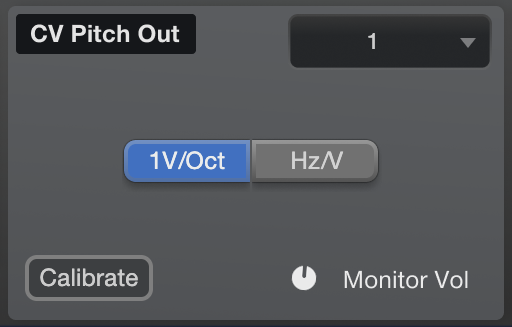
In the CV Pitch box, you can choose between two modes: 1V/oct (commonly used in modern synthesizers, including Eurorack modular systems) and Hz/volt (used for vintage synthesizers such as Korg MS-20 or Yamaha CS-10). Additionally, you can calibrate the connected oscillator pitch, ensuring your notes are properly tuned prior to recording. As an additional benefit, calibration may extend the pitch tracking range of an oscillator. For more information about these features, see the definitions below.
-
CV Pitch Output: From here, select the output channel of your audio interface that is routed to the Voltage or Octave input of your Synthesizer. The CV Pitch Output should be sent to the pitch control input of the synth. That's either 1V/Oct or Hz/Volt, depending on your synth. Make sure to use an audio interface with DC-coupled outputs. The selected channel will be exclusive for this signal.
-
1V/Oct Mode: In 1V/oct mode bipolar, DC voltages are supported. The possible voltage range (and thus the max. frequency range in octaves) depends on the used audio interface (e.g. -8V … +8V). Make sure to check if your audio interface is capable of sending analog control voltages (DC-coupled outputs). For a list of compatible PreSonus interfaces, refer to the list below.
-
Hz / Volt Mode: In Hz/volt mode, the supported range is only positive by definition.
- Calibration: The calibration button initiates the calibration process between the CV instrument and your external oscillator. When calibrating, keep the following in mind:
Press the button once to start the calibration. It will take a few seconds. Failure or success is indicated after the calibration is complete.
While the button is illuminated and flashing, the calibration process is in progress. While the calibration process is active, you can monitor the signal (if desired). There is also a level parameter to control the monitor level while calibration is active. In calibration mode, the CV Instrument will not react on keyboard inputs.
When calibration is finished, keyboard inputs will be active again. After successful calibration, the usable pitch range is evaluated. Usable in this context means that the tuning of each key is within a small tolerance. The usable range is defined by a lowest and a highest key. For example, your usable range may be from A1 to C#5. Keys that are out-of-tune are excluded. When you connect a voltage-controlled oscillator (VCO) that has a limited pitch range, the calibration will automatically seek the range that is suited best for your equipment.
Note: We recommend coarse tuning to center (C3), particularly if the oscillator has an octave switch. Additionally, to ensure the best calibration results, avoid adding modulation to the signal and calibrate with a sine waveform.
-
Monitor Volume: With the monitor volume knob, you can adjust the monitor volume in case you would like to hear the test signals while calibration is in progress. Adjusting the monitor volume knob will not change the "standard" audio signal level that will be active after calibration, and it does not change the strength of any signal routed to the hardware or back.
CV Gate
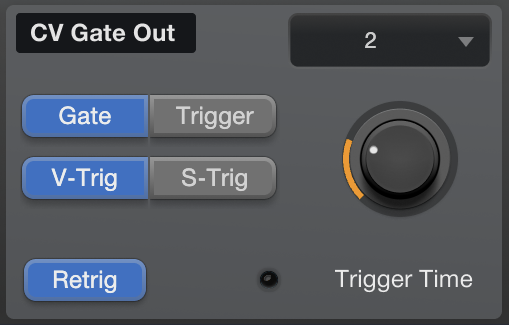
In the CV Gate box, you can send gate or trigger signals to your external synth. A trigger is started when a note is started, and it ends after the selected time. The CV Instrument supports both polarities, V-Trig and S-Trig. For more information about each of the CV Gate features, see the list below:
-
CV Gate Output: From here, select the output channel of your audio interface that is routed to the Gate or Trigger input of your Synthesizer. Route the audio output (e.g. the oscillator output of your synthesizer) to your soundcard and select the appropriate output channel. Make sure to use an audio interface with DC-coupled outputs. The selected channel will be exclusive for this signal.
-
Gate: A gate is a signal that indicates if a note is on or off on a modular synth. Gate is related to a Trigger, but sustains the signal. A gate signal is initiated when playing a note and stopped when the note is released.
-
Trigger: A trigger is a pulse with a given time length, controlled by the trigger time parameter.
-
Trigger Modes: The trigger modes are called V-Trig and S-Trig, but they apply not only for trigger signals but also for gate signals. V-Trig is the most common format, while S-Trig was used on the original Moog modular systems, such as the Minimoog Model D (S-Triggers are rarely used nowadays). See precautions below for more information about S-Trig.
-
V-Trigger (voltage trigger), or "positive trigger", holds voltage low (around 0 v), and at trigger, produces a fixed positive voltage to switch a note on. Note that the trigger voltage level differs among brands (from 2 V to 10 V). Most analog synthesizers use V-Trigger.
-
S-Trigger (short circuit trigger), or "negative trigger", holds voltage high, shorting the trigger to ground when the note should play.
-
-
Trigger Time: Active when mode "Trigger" is selected. The trigger time defines the fixed pulse length of the trigger signal and can be selected from 1ms ... 1s.
-
Retrig: When Retrigger is activated, a Moog style retrigger is sent.
Glide
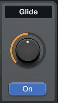
The Glide knob lets you set the rate of pitch change over time, from 1 ms to 1 second. Turn Glide on or off by pressing the button underneath the Glide knob.
Modulation
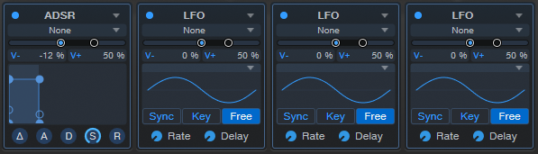
There are four modulation sources, assignable as either LFOs or ADSR envelope generators.
Each of the modules can be enabled or disabled by clicking on the blue dot located at the top left of each module. Next to the enable/disable button, there is a drop-down menu where you can choose between LFO or ADSR envelope modulation.
Additionally, each of the modules has its own CV output with a customizable voltage range. From here, select the output channel of your audio interface that is routed to the Modulation input of your Synthesizer. The selected channel will be exclusive for this module signal. The voltage signal can be easily adjusted by sliding the V-min or V-max handles along the voltage range sliders. The voltage range is -1 to +1, representing the voltages (positive or negative) that your audio interface can handle. Adjust these slider handles to shape the perfect voltage based on your interface.
LFO
LFO stands for Low Frequency Oscillator. While standard oscillators are used mainly to create audible pitched tones, LFOs create slow-moving regular cycles of control signal that are useful for modulating other parameters over time. The LFO provides Sine, Saw, Triangle, Sawtooth, Square and Random waveforms as well as a convenient Sync option to synchronize the LFO speed to the session tempo.
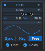
Each LFO can be shaped by editing the following controls:
-
LFO Type: Choose between Sine, Triangle, Sawtooth, Square, and Sample & Hold shapes, for the oscillation of the LFO.
-
Sync: Engage this option to enable setting LFO Rate to a rhythmic value (such as 1/8th-note or 1/4-note) relative to Session tempo. Disengage to set Rate by Hz.
-
Key: Engage this option to bind LFO speed to incoming note pitch. Higher notes result in higher LFO speeds, while lower notes result in lower LFO speeds.
-
Free: Engage this option to let the LFO run continuously, resulting in a differing LFO start point for each note played. Disengage to restart the LFO waveform at the start of each note.
-
Rate: This control lets you set the rate at which the LFO oscillates, from inaudibly low (0.01 hz) for long, sweeping changes, all the way to higher ranges (up to 8 kHz) useful for FM techniques. When the [Sync] button is engaged, Rate can be set in terms of rhythmic values relative to Session tempo, such as an 1/8th-note and 1/4-note.
-
Delay: This control lets you specify an amount of time (in milliseconds) for the LFO to wait before becoming active after a note is played. This lets you do things like adding a bit of expression to held notes, or creating layers of modulation that start at different points in each note by setting distinct Delay values for each LFO.
ADSR Envelopes
Envelope generators are a vital part of sound synthesis, giving us the ability to shape the amplitude and timbre of our sounds within the time-scale of each note. The ADSR envelopes provide control over attack, decay, sustain and release values, with customizable curve shapes on all of the time parameters.
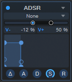
Envelope modules are triggered when a note is played. Each envelope then outputs a control signal that follows the shape set by the following controls:
-
Delay (△): This control lets you specify a length of time (in ms) for the Env to pause before starting its attack phase after a note is played. This can assist in creating evolving sounds, where cycles of modulation occur at differing times over the length of a note.
-
Attack (A): This control lets you set the time required for the envelope to go from zero (silence) to full amplitude, in a range from 0 ms to 20 seconds.
-
Decay (D): This control lets you set the time required to drop from full amplitude to the sustain level, in a range from 0 ms to 20 seconds.
-
Sustain (S): This control lets you set the signal level that is maintained from the end of the decay period, until the key is released, in a range from -∞ dB (silence) to 0.0 dB (full amplitude).
-
Release (R): This control lets you set the time required to fall back to silence after the key is released, in a range from 0 ms to 30 seconds.
Each envelope has a corresponding graphical display that represents the shape created by the settings of its parameters. There are handles on the corners and slopes of each envelope that you can click and drag, letting you shape the ADSR envelope and the curve between its points visually. If you wish to lengthen any phase of the envelope beyond the time limits of the current display, simply drag the point toward the right of the graph, and the time scale adjusts to properly display the new setting.
Virtual Keyboard

The virtual keyboard lets you easily click to play notes or manipulate the Pitch and Mod wheels, while auditioning or editing patches when you're away from a MIDI keyboard. The keyboard display also shows you which notes are currently being played.
Note that for a more playable keyboard experience when away from your MIDI controller, you can also use Fender Studio Pro's QWERTY Keyboard Device to play notes using your computer's keyboard.
Next to the virtual keyboard is the Bend parameter, which lets you set the pitch bend range of the Pitch wheel, in semitones. The upper value sets up-bend range, and the lower value sets down-bend range.
Additional Information
-
For CV Instrument to work properly, you must use an audio interface with DC coupled outputs. Various PreSonus interfaces, like the Quantum series, have this feature included. Please check your hardware documentation to ensure your interface has DC coupled outputs. To get the most out of the CV Instrument, an audio interface should provide at least 6 unused DC coupled audio outputs.
-
There are some audio interfaces that have a software mixer built in with default routing. If there is an internal mixer, this will have to be bypassed in most cases. This is the case with PreSonus interfaces: the mixer within Universal Control is on by default. If you use a PreSonus interface, open Universal Control and select Mixer Bypass while using CV Instrument.
-
Synths and synth channels are excluded from processing if the render engine detects they are not needed for the current export task. Such synths are set inactive.
Precautions
-
Eurorack signals are up to five times louder than line-level audio! Never send CV directly to your speakers. Before connecting your modular system to your audio interface, make sure to reduce the signal down to line level using a dedicated output module. Remember that direct voltage can cause damage to your speakers and hearing.
-
S-trigger is not compatible with conventional gate circuits. If you are unsure which trigger mode to use, please consult your hardware documentation.
-
Analog oscillators require some time to warm-up. Give your equipment some time to avoid temperature drift.
Compatible PreSonus and Fender Interfaces
-
Studio 26c
-
Studio 68 and 68c
-
Studio 1810 and 1810c
-
Studio 1824 and 1824c
-
Quantum TB
-
Quantum 2 TB
-
Quantum 2626
-
Quantum ES 2 / 4
-
Quantum HD 2 / 8
-
Quantum LT 16